Introduction
Parking Guidance system saves time and reduces stress for drivers.
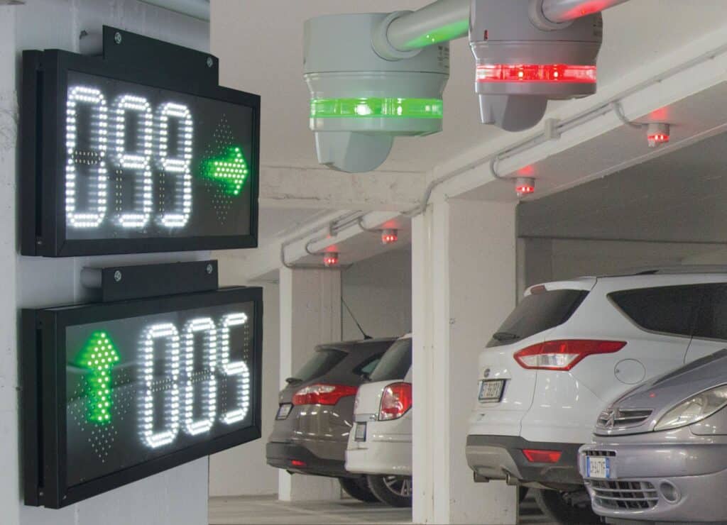
Dynamic displays strategically positioned throughout the facility provide “space available” counts and
efficiently guide the driver to open spaces with clear and bright green arrows pointing the way.
If there are no open parking spaces in an area, the sign will display a bright red cross to discourage
the drivers from entering this area. Other displays can be made to display the total number of open
spaces on a particular level or in the entire parking facility. Dynamic message displays can also be
used in the facility to provide additional information to drivers. Some examples could be Caution;
Construction Ahead; Buckle-Up, and any other message that needs to be communicated to the driv-ers in the facility.
In the parking space
Each parking space is equipped with a clear indicator light, which is green when the space is open
and red when it is occupied. If the space is for handicap parking, the colors become blue and red. The
bright LED indicators provide a visual reference as drivers seek out open parking from a distance. The
indicator lights are combined with an ultrasonic sensor as a complete set.
Parking sensors utilize a special ultrasonic frequency, much like a bat uses to search
for flying insects. A sophisticated microprocessor contained in the sensor knows how much time that
it should take for a sound wave to “bounce” from the floor back to the sensor. If a vehicle is parked
in the space, this time is measurably shortened and the logic in the microprocessor determines
that a vehicle is present in the space. Once detection has been confirmed, the indicator lights will
switch from green or blue to red and the displays and the software counts will be accurately updated
as well.
The Software…
Parking Guidance System is inherently robust and a stand-alone system. This system
does not require a PC to run. However, optional software makes it possible to monitor the real-time
situation of each parking space or level in a facility. It also has a full alarm component that can provide
logging and indication of a variety of conditions exceeding user-defined limits.
Some typical alarm functions include time-limits for individual spaces, occupied levels, and maximum
occupied indications. Additionally, the software graphically displays tables and graphs showing the
occupancy rates for the areas, the floors and the entire facility.
The software is also a tremendous tool for data logging and historical trending and analysis. Data can
be stored and utilized for multiple facilities, a single facility, a level, or even to an individual space.
The software allows authorized operators to book or reserve spaces. When an open space is booked,
the associated indicator light will turn red and it will provide a graphical link to the software.
Planning Parking Guidance System
As with any good system, the majority of the time and effort should be spent in the “planning.” An
ancient proverb says, “A good plan today is better than a perfect plan tomorrow.”
This section breaks the system planning into 5-distinct phases. These 5-phases should be completely
understood and completed before moving onto the actual Installation
5-Phases for planning Parking Guidance System
Phase 1: Gather Tools and Information • Technical drawings / information / layout of the parking system from integrator / customer.
The drawings used must always be latest version to avoid any mistakes in the work that
follows.
• The drawings should consist of lanes, cross-sections, parking spaces—for both regular and
handicap, display placement, cabinet size and placement, available power and location, and
the equipment room where the software server will be installed.
• Traffic flow: Single Direction or Bi-Directional.
• A CAD scaled drawing with information of the parking structure including lane distances for
determining the cable runs and maximum allowable sensors per master module.
• Parking space dimensions: length, width, and the distance from the floor to the ceiling. The
relationship of the floor and ceiling angle is also critical.
• The dimension from center line to center line of the spaces.
• Any information about using existing (or new if it a new building) cable trays to pull wires for
sensors.
• Prevalent codes governing the installation need to be confirmed as it will become necessary
for making a proper and legal installation.
Example of a basic facility drawing
System Description
In this chapter you will get an overview of the structure of the parking guidance system. There is a short description of the basic elements of the system, followed by a description of the structure of one system segment. Thereafter is described how the individual segments can be linked together to create a big parking guidance system with potentially thousands of spaces. Also, the network structure required to link the system to a PC with the Parking Guidance software installed is defined. Finally, the sensor calibration, sensor operation modes, and CPM operation modes are described.
Basic Modules Parking Guidance System Sensors and LED Indicators
With built-in LED indicator light, (red–green) GP 6220 2201 724
With built-in LED indicator light, (red–blue) GP 6220 2202 724
Without indicator light GP 6240 2224 724
Indicator light, red-green GP 6289 0001
Indicator light, blue-green GP 6289 0002
System structure of Parking Guidance System
At first hand, you may assume that it is a complex task to design parking guidance system
for a parking facility with hundreds or thousands of parking spaces. But when you understand the
basic structure of the system, you will realize that it is simply composed by a number of identically
structured system segments, which are linked together to create a big system. In this chapter, at first
the structure of the basic system segment is defined and then is described how the segments can be
linked together to create the overall system, including a network for central parking facility monitoring
software.
Definition of a 1-Segment System
Below a drawing of a single system segment is shown. A system segment is a local 3-wire
bus with sensors, indicators and display(s), typically monitoring one lane in the parking facility.
Fig. 24 : One-segment system
master Module with DC Power Supply
This unit generates carrier signal and DC power supply synchronization needed to create
the 3-wire bus linking all the sensors and CPM’s in the segment together. In a given segment you will
always find one – but only one – master module. 3-wire bus at segment level is referred to
as an L1 bus.
Sensors and Indicators
Each parking space belonging to the segment needs one sensor and one indicator (unless the sensor
with built-in indicator is used). Each sensor needs to be connected to the 3-wire bus and it must have
one of the 120 addresses in the range A1…O8 assigned to it for transmission of the sensor status
(occupied / not occupied) on the bus. The addresses in group P are reserved for system
purposes and cannot be used for sensors. The sensor is mounted in the middle of the parking space
and the indicator is mounted at the entry to the parking space, where it will clearly indicate to the drivers if the parking space is available or not. The two units are connected with 2 wires.
Car Park Monitor(s) (CPM) with Display(s)
Each display is controlled by a CPM, which must always be configured to operate in slave mode
when it is connected to a segment bus (L1). In slave mode, the CPM monitors a user-defined range
of parking spaces within one segment, which essentially means a range of sensor addresses (e.g. A1,
A2, and A3…A7). By reading the status of these sensor addresses, the CPM calculates the number of
open parking spaces. It sends via RS485 the result to the display, which then displays the number and
shows a dynamic green arrow. Unless of course the number is “0”. In that case red crosses will be
shown. It is possible to have several CPM modules with displays within one segment.
Another example of a 1-segment system is when we are using the 3-coloured sensor or 3-coloured
LED indicator. The 2 and 3-coloured sensor types are in general equal to each other but the 3-coloured LED indicator is different compared to the 2-coloured LED Indicator. The 3-coloured LED indicators
are bus powered just like the sensors.
The function of the 3-coloured LED is equal to the 2-coloured LED but the new indicator/sensor allows
the customer to use part of the Carpark for special parking, like for instance VIP, guest and perhaps
family parking.
This is done by using Carpark software to book these areas for special purposes. Then the drivers are
in position to find the parking places by navigating by the colors of the sensors/LED indicators.
-
للتواصل :
صفحتنا علي الفيس بوك اضغط هنا
قناتنا علي اليوتيوب اضغط هنا
صفحتنا علي تويتر اضغط هنا
صفحتنا علي الانستجرام اضغط هنا
صفحتنا علي لينكدان اضغط هنا
او بالاتصال علي الارقام الاتيه :
موبايل : 01003301525
هاتف : +24726279
واتساب : 01003301525
او بالاتصال علي ايميلات الشركه :
المبيعات والاستعلام : info@protech-eg.com
- العنوان :
- 10جمال الدين عفيفي – متفرع من حسن المأمون – مدينة نصر
- Home | شركة بروتك (protech-eg.com)
- Parking Guidance System
- Parking Guidance System
- Parking Guidance SystemParking Guidance System
- Parking Guidance SystemParking Guidance System